- 您现在的位置:买卖IC网 > Sheet目录1201 > CDB5461AU (Cirrus Logic Inc)BOARD EVAL & SOFTWARE CS5461A
�� �
�
�CS5461A�
�E1� ...�
�E2� ...�
�t� PW�
�FREQ� E�
�...�
�...�
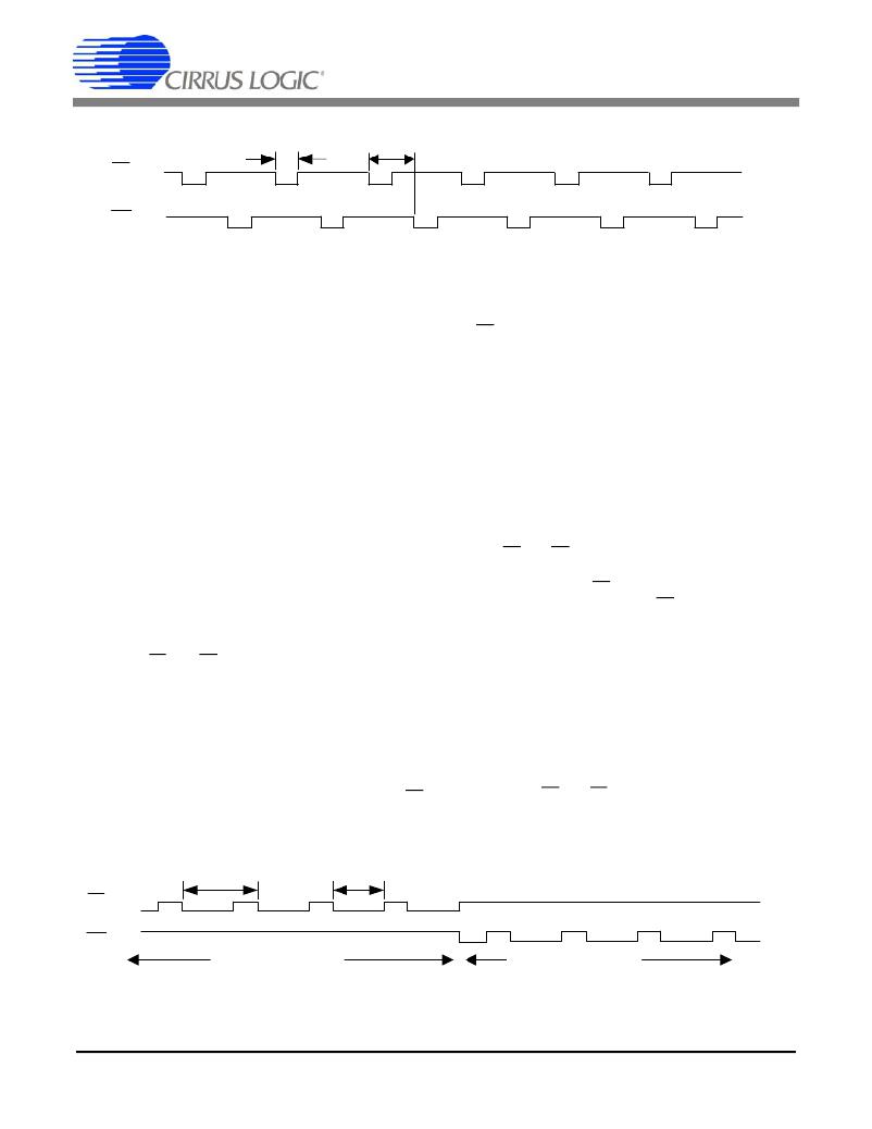
�Figure� 4.� Alternate� Pulse� Format� on� E1� and� E2�
�is� (MCLK/K)/16.� The� pulse� duration� (t� dur� )� is� an� integer�
�multiple� of� MCLK� cycles,� approximately� equal� to:�
�and� E2� output� pins� when� full-scale� input� signals� are� ap-�
�plied� to� the� voltage� and� current� channels,� then:�
�?� --------------------------------------------�
�?� ------------�
�PW�
�t� dur� ?� sec� ?�
�1�
�PulseRateE� 1� ,� 2� ?� 8�
�PulseRateE� 1� ,� 2�
�t�
�1�
�The� pulse� frequency� (FREQ� E� )� is� determined� by� the�
�-----------------------------------� ?� t� dur� ?� sec� ?� ?� -----------------------------------------�
�The� maximum� pulse� duration� (t� dur� )� is� determined� by� the�
�sampling� rate� and� the� minimum� is� defined� by� the� maxi-�
�mum� pulse� frequency.� The� t� dur� limits� are:�
�1� 1�
�(MCLK/K)/16� ?� 8� (MCLK/K)/1024� ?� 8�
�The� Pulse� Width� Register� (PW)� does� not� affect� the� nor-�
�mal� format.�
�5.4.2� Alternate� Pulse� Format�
�Setting� bits� MECH� =� 1� and� STEP� =� 0� in� the� Control�
�Register� and� ALT� =� 1� in� the� Configuration� Register� con-�
�figures� the� E1� and� E2� pins� for� alternating� pulse� format�
�output� (see� Figure� 4� ).� Each� pin� produces� alternating� ac-�
�tive-low� pulses� with� a� pulse� duration� (t� PW� )� defined� by�
�the� Pulse� Width� Register� (PW):�
�PulseRateE� 1,2� Register� and� can� be� calculated� using� the�
�transfer� function.� The� energy� direction� is� not� defined� in�
�the� alternate� pulse� format.�
�5.4.3� Mechanical� Counter� Format�
�Setting� bits� MECH� =� 1� and� STEP� =� 0� in� the� Control�
�Register� and� bit� ALT� =� 0� in� the� Configuration� Register�
�enables� E1� and� E2� for� mechanical� counters� and� similar�
�discrete� counting� instruments.� When� energy� is� nega-�
�tive,� pulses� appear� on� E2� (see� Figure� 5).� When� energy�
�is� positive,� the� pulses� appear� on� E1.� The� pulse� width� is�
�defined� by� the� Pulsewidth� Register� and� will� limit� the� out-�
�put� pulse� frequency� (FREQ� E� ).� By� default,� PW� =� 512�
�samples,� if� MCLK� =� 4.096� MHz� and� K� =� 1� then�
�t� PW� =� 128� ms.� To� ensure� that� pulses� will� occur,� the�
�PulseRateE� 1,2� Register� must� be� set� to� an� appropriate�
�value.�
�-----------------------------------------�
�t� PW� ?� ms� ?�
�=�
�PW�
�(MCLK/K)/1024�
�5.4.4� Stepper� Motor� Format�
�Setting� bits� STEP� =� 1� and� MECH� =� 0� in� the� Control�
�If� MCLK� =� 4.096� MHz,� K� =� 1,� and� PW� =� 1� then�
�t� PW� =� 0.25� ms.� To� ensure� that� pulses� occur� on� the� E1�
�Register� and� bit� ALT� =� 0� in� the� Configuration� Register�
�configures� the� E1� and� E2� pins� for� stepper� motor� format.�
�When� the� accumulated� active� power� equals� the� defined�
�FREQ� E�
�t� PW�
�E1�
�...�
�...�
�E2�
�...�
�Positive� Energy�
�Negative Energy�
�...�
�Figure� 5.� Mechanical� Counter� Format� on� E1� and� E2�
�DS661F3�
�17�
�发布紧急采购,3分钟左右您将得到回复。
相关PDF资料
CDB5466U
BOARD EVAL & SOFTWARE CS5466 ADC
CDB5467U
BOARD EVAL FOR CS5467 ADC
CDB5560-2
DEV BOARD FOR CS5560 W/SE INPUT
CDB5571-2
DEV BOARD FOR CS5571 W/SE INPUT
CDB8422
BOARD EVAL FOR CS8422 RCVR
CDB8952T
BOARD EVAL FOR CS8952
CDCE906-706PERFEVM
EVAL MOD PERFORMANCE CDCE906/706
CEVAL-033
BOARD EVAL FOR CVCO33 .3"X.3"
相关代理商/技术参数
CDB5461AU-Z
制造商:Cirrus Logic 功能描述:PB-FREEEVAL BOARD FOR CS5461 WITH USB - Bulk
CDB5462
制造商:Cirrus Logic 功能描述:EVAL BOARD FOR CS5462 - Bulk
CDB5463U
功能描述:数据转换 IC 开发工具 Eval Bd Sngl-Phase Pow/Energy
RoHS:否 制造商:Texas Instruments 产品:Demonstration Kits 类型:ADC 工具用于评估:ADS130E08 接口类型:SPI 工作电源电压:- 6 V to + 6 V
CDB5463U-Z
功能描述:EVAL BOARD USB FOR CS5463 RoHS:是 类别:编程器,开发系统 >> 评估板 - 模数转换器 (ADC) 系列:- 产品培训模块:Obsolescence Mitigation Program 标准包装:1 系列:- ADC 的数量:1 位数:12 采样率(每秒):94.4k 数据接口:USB 输入范围:±VREF/2 在以下条件下的电源(标准):- 工作温度:-40°C ~ 85°C 已用 IC / 零件:MAX11645 已供物品:板,软件
CDB5464U
功能描述:数据转换 IC 开发工具 Eval Bd 3-Ch Sngl-Phs Pow/Energy
RoHS:否 制造商:Texas Instruments 产品:Demonstration Kits 类型:ADC 工具用于评估:ADS130E08 接口类型:SPI 工作电源电压:- 6 V to + 6 V
CDB5464U-Z
制造商:Cirrus Logic 功能描述:EVAL BD PB-FREE DEMO BOARD FOR CS5464 - Boxed Product (Development Kits) 制造商:Cirrus Logic 功能描述:Eval Board
CDB5466U
功能描述:数据转换 IC 开发工具 Eval Bd F/Residental Pow-Meter Apps
RoHS:否 制造商:Texas Instruments 产品:Demonstration Kits 类型:ADC 工具用于评估:ADS130E08 接口类型:SPI 工作电源电压:- 6 V to + 6 V
CDB5466U-Z
制造商:Cirrus Logic 功能描述:PB-FREEEVAL BOARD FOR CS5466 WITH USB - Bulk